Design for Injection Molding
Overview
Design for Manufacturing (DFM) ensures parts can be efficiently and economically produced. For injection molding, key principles are:
- Uniform wall thickness
- Proper draft angles
- Appropriate ribs and bosses
- Radii and fillets
- Avoiding undercuts
Wall Thickness
Uniform Walls

The most important DFM rule: maintain uniform wall thickness throughout the part.
Why Uniformity Matters:- Uneven cooling causes warpage
- Thick sections cause sink marks
- Thick sections extend cycle time
- Flow imbalances cause weld line issues
| Material | Typical Range (mm) |
|---|---|
| PP | 1.0-3.0 |
| ABS | 1.5-3.5 |
| PA66 | 1.0-3.0 |
| PC | 1.5-4.0 |
| PEEK | 1.5-4.5 |
Transitioning Thickness
When thickness changes are unavoidable:
Sponsored
175+ hours of industry projects & 12 IIT faculty sessions
Master CATIA, NX, LS-DYNA, HyperMesh and more
View Full Curriculum
- Gradual transitions (3:1 slope minimum)
- Never abrupt steps
- Locate transitions away from stress areas
Draft Angles
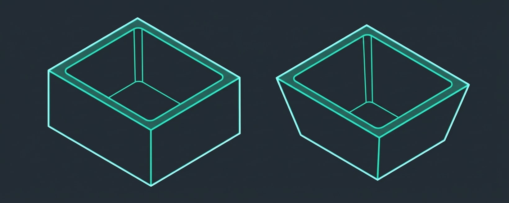
Draft is a slight taper on vertical walls that allows the part to release from the mold.
Why Draft is Needed:- Part shrinks onto core during cooling
- Without draft, ejection force can damage part
- Vacuum can form between part and mold
| Surface | Minimum Draft |
|---|---|
| Smooth surfaces | 0.5-1° |
| Textured surfaces | 1-2° + 1° per 0.025mm texture depth |
| Deep ribs | 1-2° |
| Shutoffs | 3-5° |
Ribs
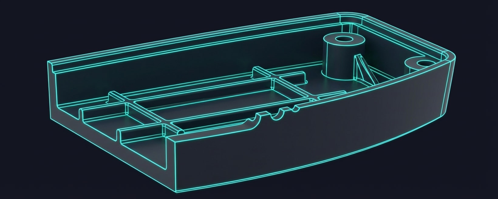
Ribs add stiffness without increasing wall thickness.
Design Guidelines
| Parameter | Guideline |
|---|---|
| Thickness | 50-60% of wall thickness |
| Height | ≤3× wall thickness |
| Draft | 0.5-1° per side |
| Base radius | 0.25-0.5× wall thickness |
| Spacing | ≥2× wall thickness apart |
- Thicker ribs cause sink marks on opposite surface
- Thinner ribs may not fill properly
Rib Orientation
- Perpendicular to load for bending resistance
- Crosshatch pattern for bidirectional stiffness
- Consider flow direction during fill
Bosses
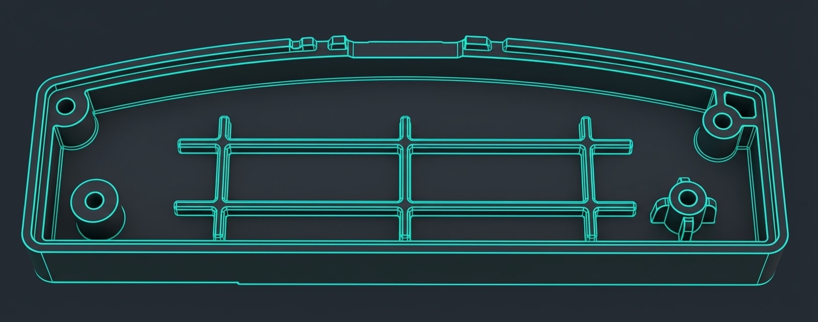
Bosses provide mounting points for screws, pins, or inserts.
Sponsored
Ranjith switched from IT to core automotive industry
His inspiring career transition story with video
See His Journey
Design Guidelines
| Parameter | Guideline |
|---|---|
| OD | 2-2.5× screw diameter |
| Wall thickness | 50-60% of nominal wall |
| Height | ≤2.5× OD |
| Draft | 0.5° minimum on OD and ID |
| Base radius | 0.25× wall minimum |