The Feature Control Frame
What is a Feature Control Frame?
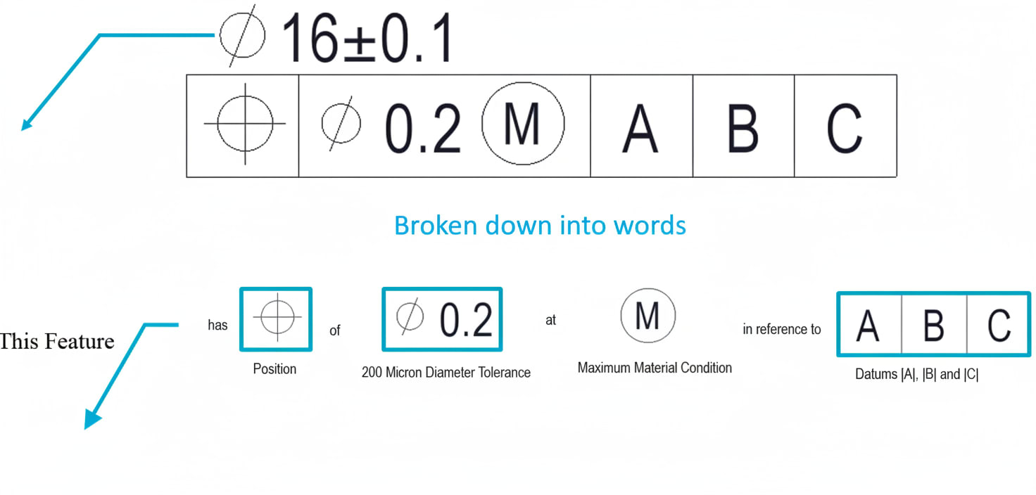
The Feature Control Frame (FCF) is the rectangular box that contains all GD&T information for a specific tolerance. It's the fundamental building block of GD&T notation.
Every FCF reads left to right and contains up to four compartments:
┌──────────┬──────────┬────────┬────────┬────────┐
│ Symbol   │ Tolerance│ Datum A│ Datum B│ Datum C│
└──────────┴──────────┴────────┴────────┴────────┘
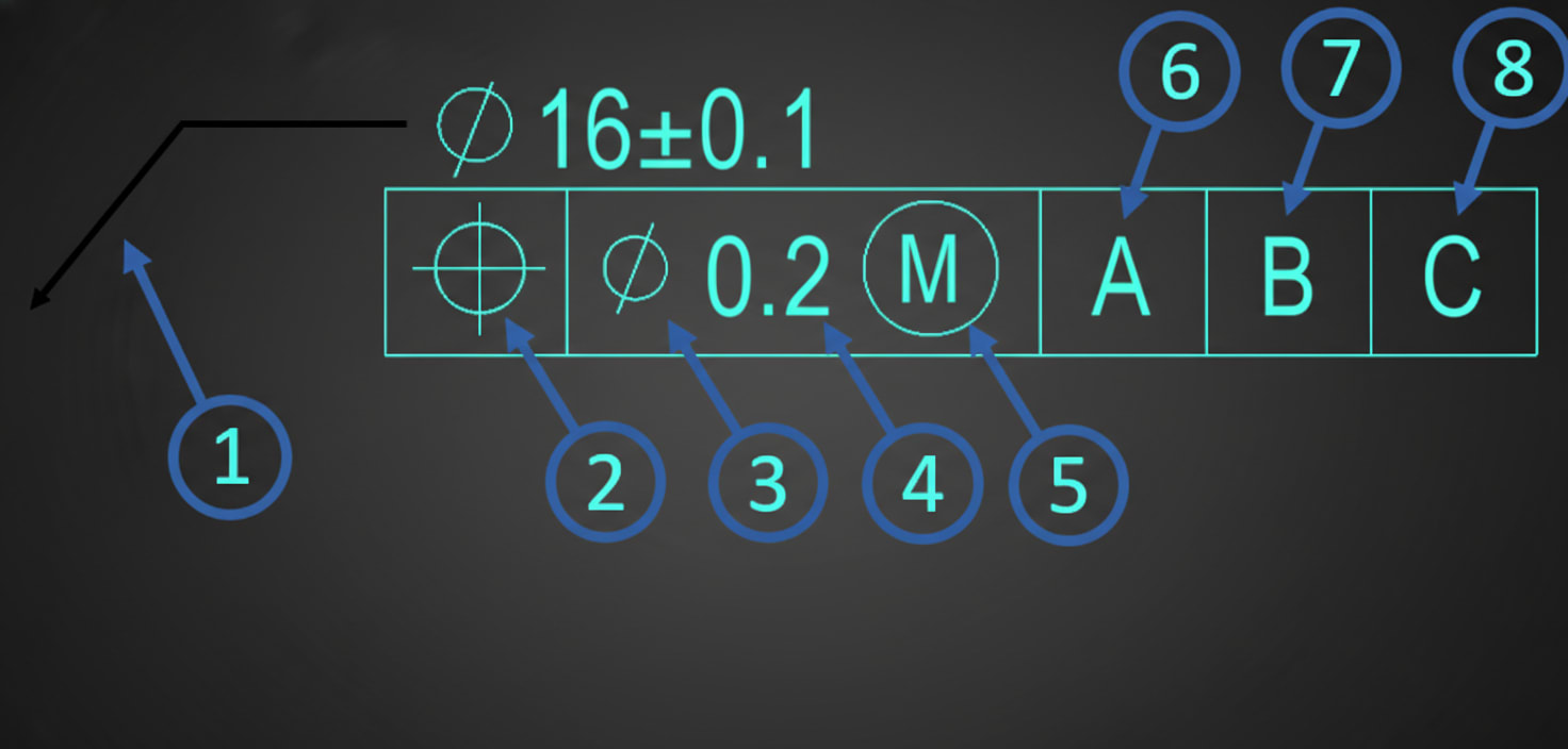
The Four Compartments
1. Geometric Characteristic Symbol
The first compartment contains the symbol indicating WHAT type of control:
Sponsored
April batch closing soon — only 42 seats remaining
Join 3,000+ engineers who got placed at top companies
Reserve Your Seat
| Symbol | Name | Category |
|---|---|---|
| ─ | Straightness | Form |
| ▭ | Flatness | Form |
| ○ | Circularity | Form |
| ⌭ | Cylindricity | Form |
| ∠ | Angularity | Orientation |
| ∥ | Parallelism | Orientation |
| ⊥ | Perpendicularity | Orientation |
| ⊕ | Position | Location |
| ⌓ | Profile of Line | Profile |
| ⌔ | Profile of Surface | Profile |
| ↗ | Circular Runout | Runout |
| ↗↗ | Total Runout | Runout |
2. Tolerance Value
The second compartment specifies HOW MUCH variation is allowed:
┌──────────┬──────────────────┐
│ ⊕        │ ⌀ 0.25 (M)       │
└──────────┴──────────────────┘
This compartment may include:
- ⌀ (diameter symbol) - indicates cylindrical tolerance zone
- Numeric value - the tolerance amount in drawing units
- Material condition modifier - (M), (L), or (S)
3-5. Datum References
The remaining compartments specify the datum reference frame - the features used as reference points:
Sponsored
Abhishek landed his dream job at TATA ELXSI
From learning simulations to working at an industry leader
See His Journey
┌──────────┬──────────┬────────┬────────┬────────┐
│ ⊥        │ 0.1      │ A      │ B      │ C      │
└──────────┴──────────┴────────┴────────┴────────┘- Primary datum (A) - First point of contact, removes 3 degrees of freedom
- Secondary datum (B) - Second constraint, removes 2 degrees of freedom
- Tertiary datum (C) - Final constraint, removes 1 degree of freedom
Note: Form controls (straightness, flatness, circularity, cylindricity) do NOT reference datums—they control the feature's shape independent of other features.