Material Condition Modifiers
What are Material Condition Modifiers?
Material condition modifiers define how geometric tolerance relates to the actual size of a feature. They can provide "bonus tolerance" that increases the allowable variation as a feature departs from its maximum or minimum material condition.The three modifiers are:
| Symbol | Name | Meaning |
|---|---|---|
| Ⓜ or (M) | Maximum Material Condition | Bonus as feature departs from MMC |
| Ⓛ or (L) | Least Material Condition | Bonus as feature departs from LMC |
| Ⓢ or (S) | Regardless of Feature Size | No bonus (RFS is default) |
Understanding Material Conditions
For a Hole (Internal Feature)
- MMC = Smallest hole (most material remaining)
- LMC = Largest hole (least material remaining)
┌─────┐ ┌─────┐ ┌─────┐
│ ○ │ │ ○ │ │ ○ │
│small│ │ nom │ │large│
└─────┘ └─────┘ └─────┘
MMC Nominal LMC
For a Shaft (External Feature)
- MMC = Largest shaft (most material)
- LMC = Smallest shaft (least material)
┌─────┐ ┌─────┐ ┌─────┐
│ ███ │ │ ██ │ │ █ │
│large│ │ nom │ │small│
└─────┘ └─────┘ └─────┘
MMC Nominal LMC
MMC (Ⓜ) - Maximum Material Condition
The Concept
MMC provides bonus tolerance when a feature is NOT at its maximum material condition. The logic: if the hole is bigger (or shaft is smaller), there's more clearance for assembly, so position can be relaxed.
Example: Hole with MMC
Hole size: ⌀ 10.0 ± 0.2 (9.8 to 10.2)
Position: ⌀ 0.25 (M)
MMC = 9.8mm (smallest hole)
Bonus Tolerance Calculation:
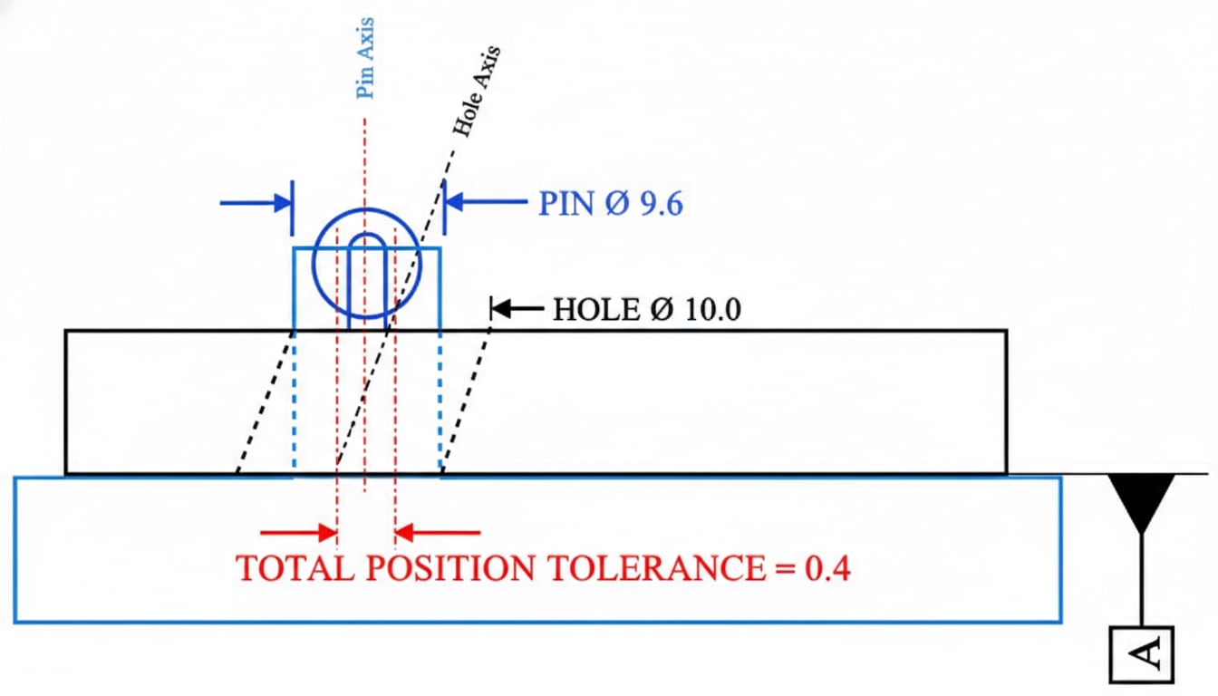
| Actual Hole | Departure from MMC | Bonus | Total Position Tol. |
|---|---|---|---|
| 9.8 (MMC) | 0 | 0 | 0.25 |
| 9.9 | 0.1 | 0.1 | 0.35 |
| 10.0 | 0.2 | 0.2 | 0.45 |
| 10.1 | 0.3 | 0.3 | 0.55 |
| 10.2 (LMC) | 0.4 | 0.4 | 0.65 |
Total Tolerance = Stated Tolerance + (Actual Size - MMC Size)
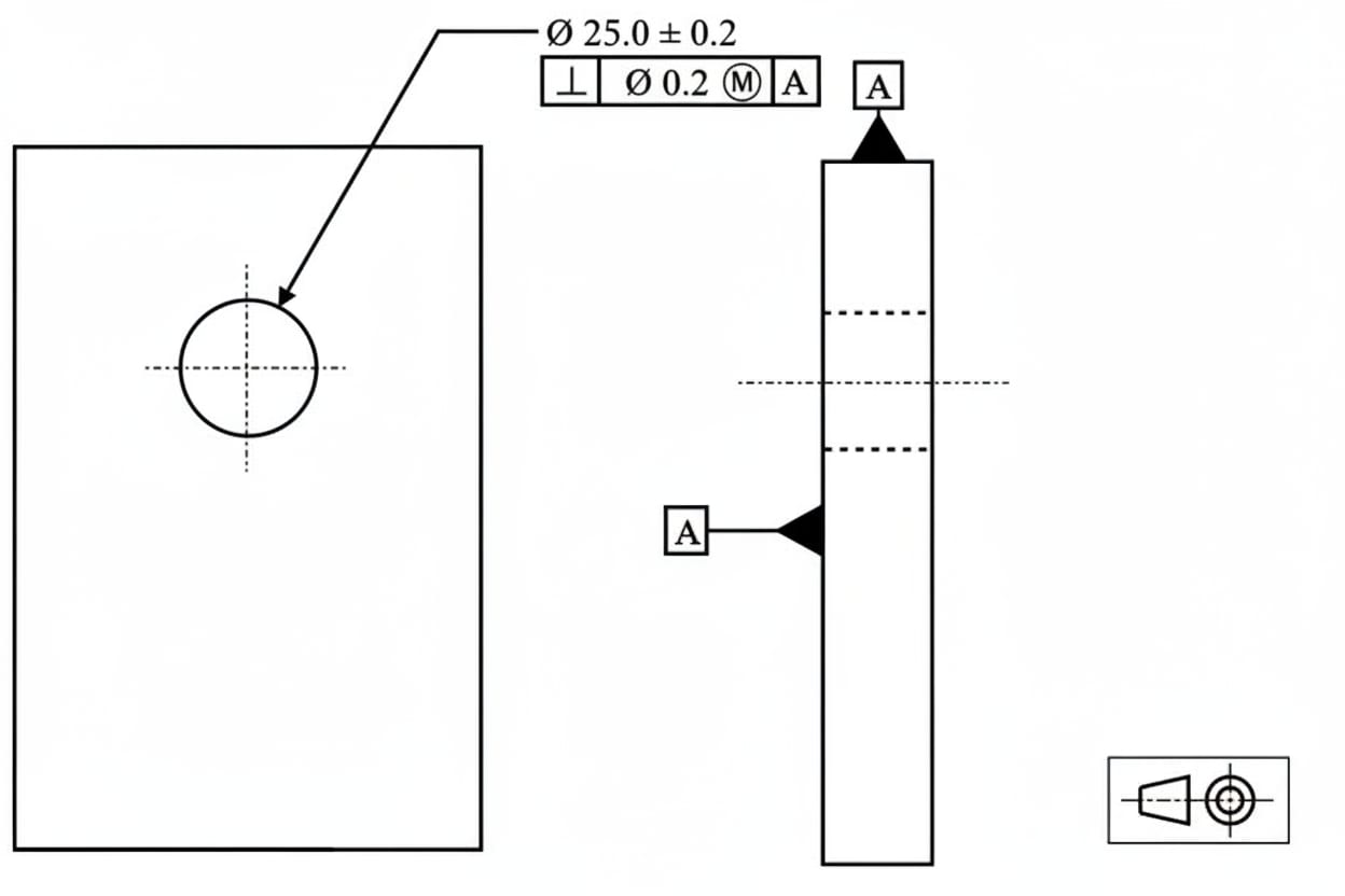
LMC (Ⓛ) - Least Material Condition
The Concept
LMC provides bonus tolerance as a feature approaches maximum material. Used when minimum wall thickness or edge distance is critical.
Get up to ₹60,000 off with Founder's Scholarship
Harshal
Fiat Chrysler
Abhishek
TATA ELXSI
Srinithin
Xitadel
Ranjith
Core Automotive
Gaurav
Automotive Company
Bino
Design Firm
Aseem
EV Company
Puneet
Automotive Company
Vishal
EV Startup
More Success Stories
Only 42 seats left for the April batch
Example: Hole Near an Edge
Hole size: ⌀ 10.0 ± 0.2 (9.8 to 10.2)
Position: ⌀ 0.30 (L)
LMC = 10.2mm (largest hole)
Bonus Tolerance Calculation:
| Actual Hole | Departure from LMC | Bonus | Total Position Tol. |
|---|---|---|---|
| 10.2 (LMC) | 0 | 0 | 0.30 |
| 10.1 | 0.1 | 0.1 | 0.40 |
| 10.0 | 0.2 | 0.2 | 0.50 |
| 9.9 | 0.3 | 0.3 | 0.60 |
| 9.8 (MMC) | 0.4 | 0.4 | 0.70 |
- Maintaining minimum wall thickness
- Ensuring minimum edge distance
- Thread engagement requirements
RFS (Ⓢ) - Regardless of Feature Size
The Concept
RFS means the tolerance applies at any size—no bonus tolerance is available. This is the default condition when no modifier is specified.
┌───┬────────┬────────┐ ┌───┬──────────┬────────┐
│ ⊕ │ 0.25 │ A │ = │ ⊕ │ 0.25 (S) │ A │
└───┴────────┴────────┘ └───┴──────────┴────────┘
(implied RFS) (explicit RFS)
Use Cases:
- Critical interfaces where bonus cannot be allowed
- Precision alignment features
- Non-mating features
MMC Modifier on Datums
The modifier can also apply to datum references:
┌───┬────────────┬──────────┐
│ ⊕ │ ⌀ 0.25 (M) │ A (M) │
└───┴────────────┴──────────┘
Datum shift: When datum feature B departs from MMC, the part can shift within the functional gage, providing additional tolerance.
Virtual Condition
For MMC:
- External feature VC = MMC + Geometric Tolerance
- Internal feature VC = MMC - Geometric Tolerance
Example: Pin
Size: ⌀ 10.0 ± 0.1 (MMC = 10.1)
Position: ⌀ 0.2 (M)
Virtual Condition = 10.1 + 0.2 = ⌀ 10.3
For LMC:
- External feature VC = LMC - Geometric Tolerance
- Internal feature VC = LMC + Geometric Tolerance
When to Use Each Modifier
| Modifier | Use When |
|---|---|
| MMC (M) | Assembly fit is the primary concern |
| LMC (L) | Minimum material (wall thickness, edge distance) is critical |
| RFS (S) | Precise alignment required regardless of size |
Modifiers Allowed by Control Type
| Control | MMC/LMC Allowed? |
|---|---|
| Form controls | No (no feature of size) |
| Orientation | Yes (on features of size) |
| Position | Yes (most common) |
| Profile | Yes (2018 standard) |
| Runout | No (must be RFS) |
Key Takeaways
- MMC = Maximum Material Condition (smallest hole, largest shaft)
- LMC = Least Material Condition (largest hole, smallest shaft)
- RFS = Regardless of Feature Size (default, no bonus)
- Bonus tolerance = actual departure from MMC or LMC
- MMC is most common—used for assembly fits
- LMC is used for minimum wall/edge requirements
- Virtual condition defines worst-case boundary
---
Next Lesson: Quiz - Test your GD&T knowledge!