Introduction to GD&T
What is GD&T?
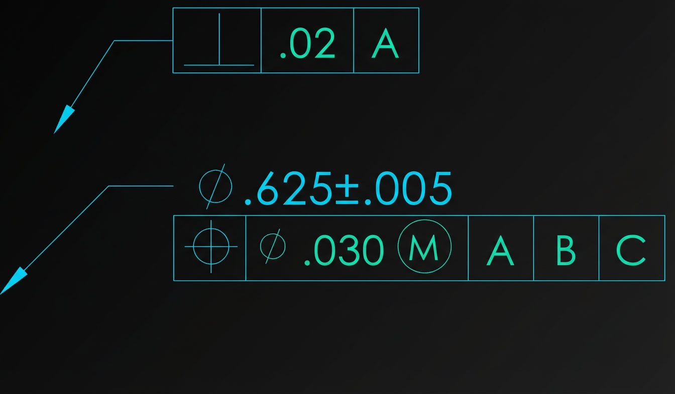
Geometric Dimensioning and Tolerancing (GD&T) is a standardized symbolic language used on engineering drawings to communicate design intent precisely. It defines not just the size of features, but also their form, orientation, location, and runout relative to other features.Think of GD&T as a universal language that allows engineers, manufacturers, and inspectors worldwide to understand exactly what a part should look like and how much variation is acceptable.
Why Does GD&T Exist?
Traditional coordinate tolerancing (using ± values) has limitations:
| Traditional Tolerancing | GD&T |
|---|---|
| Square tolerance zones | Cylindrical zones (58% more area) |
| Ambiguous datum references | Explicit datum hierarchy |
| Multiple interpretations | Single, clear interpretation |
| Over-constrains parts | Allows functional variation |
The Governing Standard: ASME Y14.5
The ASME Y14.5 standard is the authoritative guideline for GD&T in North America. The current edition is Y14.5-2018 (reaffirmed 2024).
Sponsored
Ranjith switched from IT to core automotive industry
His inspiring career transition story with video
See His Journey
Key sections of the standard:
- Section 5: Form tolerances
- Section 6: Orientation tolerances
- Section 7: Location tolerances
- Section 8: Profile tolerances
- Section 9: Runout tolerances
Note: ISO also has GD&T standards (ISO 1101, etc.) with slight differences. This course focuses on ASME Y14.5.