Orientation Controls
What are Orientation Controls?
Orientation controls define how a feature's angle or direction relates to a datum reference frame. Unlike form controls, orientation controls always reference at least one datum.There are three orientation controls:
| Symbol | Name | Controls |
|---|---|---|
| ∥ | Parallelism | Surface or axis parallel to datum |
| ⊥ | Perpendicularity | Surface or axis 90° to datum |
| ∠ | Angularity | Surface or axis at specified angle |
1. Parallelism (∥)
Definition: Controls how parallel a surface or axis must be to a datum.Surface Parallelism
The surface must lie between two parallel planes that are parallel to the datum:
FCF: ┌───┬──────┬────────┐
     │ ∥ │ 0.1  │ A      │
     └───┴──────┴────────┘

    Datum A ═══════════════════════

         ═══════════════ 0.1 tolerance zone
    ~~~~~~~~~~~~~~~~~~~~ (actual surface)
         ═══════════════
Axis Parallelism
When applied to a feature of size, the axis must lie within a cylindrical zone parallel to the datum:
Sponsored
Get up to ₹60,000 off with Founder's Scholarship
Only 42 seats left for the April batch
Check Eligibility
FCF: ┌───┬────────┬────────┐
     │ ∥ │ ⌀ 0.1  │ A      │
└───┴────────┴────────┘2. Perpendicularity (⊥)
Definition: Controls how perpendicular (90°) a surface or axis must be to a datum.Surface Perpendicularity
The surface must lie between two parallel planes perpendicular to the datum:
FCF: ┌───┬──────┬────────┐
     │ ⊥ │ 0.08 │ A      │
     └───┴──────┴────────┘

                │ │ 0.08 zone
    Datum A ════╪═╪════════════
                │ │
                │ │ (actual surface)
Axis Perpendicularity
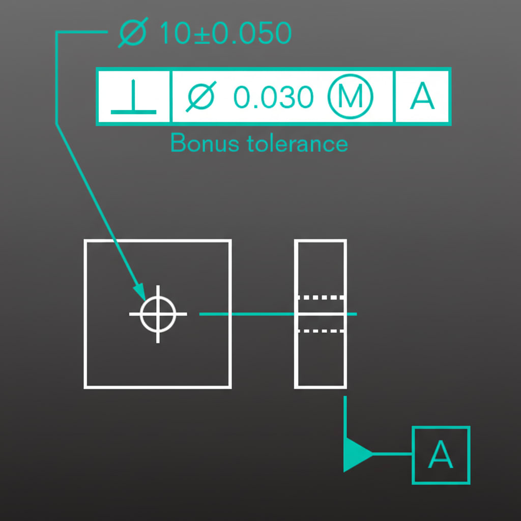
The axis must lie within a cylindrical zone perpendicular to the datum plane:
FCF: ┌───┬────────┬────────┐
│ ⊥ │ ⌀ 0.1 │ A │
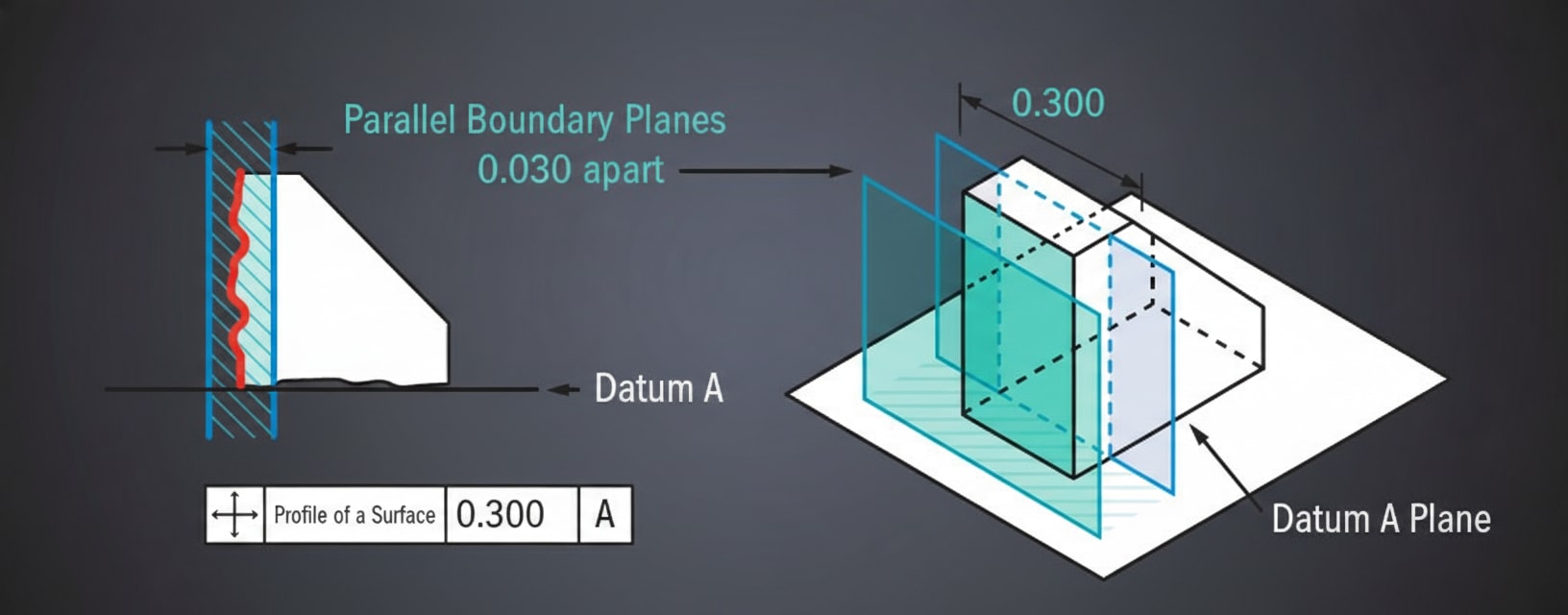
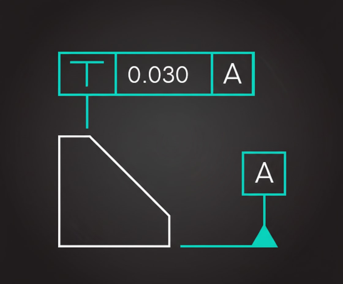
└───┴────────┴────────┘3. Angularity (∠)
Definition: Controls a surface or axis at any angle other than 0° or 90° to a datum.FCF: ┌───┬──────┬────────┐
│ ∠ │ 0.1 │ A │
└───┴──────┴────────┘
Basic angle: 45°
╲
╲ 0.1 tolerance zone
Datum A ═══╲═════════════
╲ 45°Important: The basic angle (e.g., 45°) is shown separately on the drawing, not in the FCF. The FCF only shows the tolerance.Use Case: Chamfers, tapered features, angled mounting surfaces.